

EV charging load balancing: how to stay within your grid connection

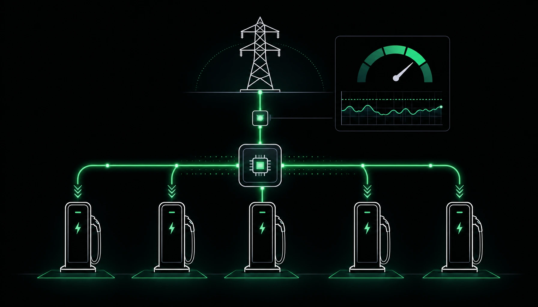
Installing a charging station is the easy part. The real problem appears when the number of cars in the car park grows while the grid connection capacity stays the same. Five 22 kW AC stations mean 110 kW of demand — while an office building may have only 40 kW contracted. Upgrading a grid connection often means months of paperwork with the distribution system operator (DSO), a connection cost in the tens of thousands of euros, and sometimes a physical lack of capacity at that point in the grid. Fortunately, in the vast majority of installations a connection upgrade is not needed at all.
The answer is load balancing — dynamic management of charging power. This article covers the topic end to end: the difference between static and dynamic load management (DLM), how it works technically at the OCPP protocol level (with concrete messages), what phase balancing is, how power sharing works on DC stations, and how to choose hardware and configuration for different sites — so you can charge many cars at once without tripping breakers or paying penalties for exceeding your contracted capacity.
What load balancing is
Load balancing is a mechanism that continuously divides the available electrical power between active charging stations so their combined draw never exceeds a defined limit — whether a circuit breaker or the contracted capacity of the whole site. Instead of giving every station full power regardless of the rest, the system controls it: lowering power when many cars are charging, and raising it when some finish or when the building frees up capacity.
There is one fact to grasp from the start, because it causes the most confusion:
Load balancing does not create extra power. It caps peak draw so you fit within what you already have.
In other words, load balancing lets you make better use of your existing connection, not bypass its physical limits. If you have 40 kW, then 40 kW gets divided; it will not turn into 110 kW. But because in practice cars rarely all charge at once at full power — and even more rarely do so at the exact moment of the building's consumption peak — a well-configured load balancing setup can serve many times more points than a simple multiplication of nominal station power would suggest.
To size the real number of stations on a given connection, engineers use the diversity factor. For an office car park with multi-hour charging, values of around 0.3–0.5 are common — meaning an installation designed with dynamic load management actually needs 2–3 times less connection capacity than the sum of the nominal power of all points.
Why this is a problem: connection capacity vs number of stations
Let's put numbers on it. A typical AC station is 11 kW (3×16 A) or 22 kW (3×32 A). A DC station is already 50, 150, even 350–400 kW. A handful of points is enough to overshoot a site's connection capacity:
- 4 × AC 22 kW = 88 kW,
- 8 × AC 11 kW = 88 kW,
- 2 × DC 150 kW = 300 kW,
- 1 × DC 350 kW = 350 kW (as much as many a small factory).
When stations start simultaneously without power management, one of two things happens. Either you exceed the overcurrent protection and trip the main breaker — cutting power to part or all of the building, not just the chargers. Or you exceed the contracted capacity and the DSO charges penalty fees for exceeding ordered capacity — usually a multiple of the standard rate for every kW of overshoot in the billing period. Both are common in practice in company car parks and underground garages, where the electrical installation was never designed for several cars charging at once.
That is why, when planning infrastructure — especially where the charging-point obligation for non-residential buildings applies — load balancing is not an add-on but a condition for the whole thing to run stably and legally. A designer who writes "N stations × nominal power" without load balancing either overstates the required connection capacity or designs an installation that will trip breakers on the first busy morning.
Static vs dynamic load management
This is the most important distinction and the most common investor question. Load balancing comes in two variants that differ in how smart they are and how fully they use the connection.
Static load balancing
In the static variant, the installer sets a fixed limit for a group of stations. Example: you reserve 40 kW for charging and have four stations — static load balancing divides those 40 kW, e.g. dynamically between active sessions (two cars get 20 kW each; four cars get 10 kW each), but the sum never exceeds the hard-set 40 kW, regardless of what happens in the rest of the building.
Advantages: simple, cheap, no metering of the whole site or extra meter on the connection. The key drawback: the system cannot see the rest of the building. The 40 kW reserve must be carved out "hard" and subtracted from the power available to other loads — which often means the reserve is either too cautious (power wasted in the evening when the building is empty) or too bold (during the day, at full building load, the sum still risks an overshoot).
Static load management is enough where charging has a separate, predictable power reserve and does not really compete with other loads — e.g. a dedicated circuit for a carport on a connection with spare capacity.
Dynamic load management (DLM)
In the dynamic variant, the system measures the whole site's draw in real time — usually via a meter or current transformers (CT clamps) on the main connection — and gives stations exactly as much power as is free under the set limit. When the building draws more (a lift starts, an AC compressor, a production line), dynamic load management immediately throttles charging. When the building's demand drops, stations get more and cars charge faster.
Formally, DLM enforces a simple but critical inequality at every moment:
building_power + charging_power ≤ contracted_capacity (with a safety margin)
This fully uses the connection and protects it from overshoot under all conditions, including emergencies. It requires metering on the connection and a system to process that data and turn it into commands — but in return it delivers the maximum the installation can give, without the risk of tripping breakers and without over-ordering capacity "just in case".
| Feature | Static | Dynamic (DLM) |
|---|---|---|
| Power limit | fixed, set manually | variable, in real time |
| Sees building consumption | no | yes (metering on connection) |
| Use of the connection | partial (a "hard" reserve) | maximal |
| Requires site metering | no | yes (meter / CT) |
| Protection from exceeding contracted capacity | only within the reserve | full |
| Cost / complexity | low | higher |
| When to choose | separate, predictable reserve | charging competes with the building |
In practice, most commercial sites — offices, hotels, malls, factories, housing communities — share the connection between charging and the rest of the building, so they need dynamic load management. Static works for simpler, dedicated installations or as a cheap first stage that is later upgraded to DLM.
How it works technically: OCPP Smart Charging
For load balancing to work across stations — often from different manufacturers — you need a common language. That language is OCPP (Open Charge Point Protocol), an open standard for communication between the charge point and the charging management system (CSMS), developed by the Open Charge Alliance. We cover the protocol and its role in vendor independence in the post on the OCPP protocol. Here we focus on the part that delivers load balancing: the Smart Charging feature profile.
The charging profile and SetChargingProfile
At the heart of Smart Charging is the SetChargingProfile message. With it, the CSMS imposes on the station a power or current limit that applies at a given moment. The station applies this limit to the ongoing session (passing it to the car via the pilot signal per IEC 61851 / ISO 15118) and the car adjusts its draw. When the situation changes, the system sends a new profile and the power split updates within seconds.
The OCPP 1.6 specification (the "Smart Charging" chapter) states the purpose of this feature outright:
"The Smart Charging functionality within OCPP aims to support the following use cases: […] load balancing at a site with multiple Charge Points."
The profile hierarchy is key. OCPP defines three profile purposes (chargingProfilePurpose) that stack on top of each other:
ChargePointMaxProfile— a hard limit for the whole station (all its connectors together). This enforces the limit at the level of the physical protection or the power allocated to the location.TxDefaultProfile— the default profile for every new session on a connector (e.g. "every car starts at max 11 kW").TxProfile— the profile of a specific, ongoing transaction; it overrides the default for that one session.
The effective limit at any moment is the minimum of all applicable profiles — which lets you hold a site-wide cap and steer individual sessions at the same time.
Schedule, units and number of phases
Inside a profile is a schedule (chargingSchedule) made of periods (chargingSchedulePeriod). Each period defines:
limit— the allowed draw value,chargingRateUnit— the unit:A(amps per phase) orW(watts),numberPhases— the number of phases the car may draw on (important for phase balancing),startPeriod— the moment from which the period applies.
The choice of unit is not cosmetic. Controlling in amps per phase is natural for protecting circuit breakers (a fuse acts on current, not power), whereas controlling in watts better suits a site-wide contracted-capacity limit. A good DLM system handles both and converts between them, accounting for voltage and phase count.
It is also worth knowing the lower bound: IEC 61851 does not allow AC charging below 6 A per phase (~1.4 kW at 230 V single-phase). Below that you cannot "throttle" a car — you have to pause it or use queuing. That is why, with very many points on a weak connection, load balancing must be able not only to lower power but also to temporarily pause sessions.
Reading and clearing profiles
To round it off, Smart Charging adds two useful operational messages:
GetCompositeSchedule— lets the CSMS ask the station for the composite schedule (the combination of all profiles) for the upcoming period. Invaluable when diagnosing "why is this car charging slower than it should".ClearChargingProfile— removes applied profiles (e.g. to lift a limit once the peak has passed).
What OCPP 2.0.1 changes
In OCPP 2.0.1, Smart Charging gains much more than one-way limit setting. It adds two-way negotiation of the car's needs via ISO 15118: the station sends the CSMS a NotifyEVChargingNeeds message (how much energy the car needs and by when) and NotifyEVChargingSchedule, and the system can factor this into the charging plan for the whole location. This opens the door to smart queuing ("this car leaves at 8:00 and needs 30 kWh — it has priority over one parked until evening") and to integration with dynamic tariffs and solar PV. We cover the differences between protocol versions separately — here it's enough to remember that the newer the OCPP, the richer the load-balancing toolset.
Because OCPP is open and supported by most manufacturers, all this control can span stations from different brands connected to a single system — you are not locked to one hardware vendor. It is the same principle behind open infrastructure: you choose hardware for the real needs of the site, and a shared charge point management system ties it together. In this model the CSMS is the "brain" — it collects the connection metering, computes the split and sends SetChargingProfile to the stations over OCPP. Load balancing becomes a software function, not a feature of a single charger.
Phase balancing: single-phase vs three-phase
A separate, often overlooked element of load balancing is phase balancing. A three-phase installation has three phases (L1, L2, L3), and cars can be single- or three-phase — and it is the car maker, not the station, that decides how many phases the onboard charger actually uses. Many popular models charge AC only single- or two-phase.
The problem: if several single-phase cars "sit" on the same phase (because that is how the stations were wired), that phase is overloaded while the other two are nearly empty. In theory the power is there in the connection, but the breaker on the overloaded phase will trip — because a fuse reacts to the current on its phase, not the sum of three. On top of that comes grid asymmetry (imbalance), which the DSO dislikes and which in extreme cases is limited contractually.
Smart stations and systems apply inter-phase balancing in two ways:
- Phase assignment — at installation, single-phase points are spread evenly: the first on L1, the second on L2, the third on L3, the fourth back on L1 (so-called phase rotation in the wiring).
- On-the-fly control — knowing (via OCPP and metering) the load on each phase, the system sets
numberPhaseslimits and current per session to even out L1/L2/L3, and some stations can even switch the supply phase for a car.
The effect is twofold: a lower risk of exceeding the protection on a single phase, and a shorter real charging time, because the available power is used symmetrically rather than blocked on one overloaded phase. It is a nuance easy to miss at the design stage, yet it decides how many cars an installation can serve without an upgrade.
Load balancing across different station types
Load balancing looks different depending on your hardware — one reason to choose stations with the whole site in mind, not a single point. We cover the difference between technologies in the post on how to choose a charging station (AC or DC); below is how the power split works in each case.
AC stations (office, housing community, staff car park)
The most common and most rewarding case for load balancing. Several to a dozen AC points on one connection, multi-hour charging — cars stand all night or a full working day. Since a car stands for 8 hours but needs 3–4 hours at full power to "top up", the system has a huge margin: it can spread energy so that all cars leave charged while the connection never nears its limit. Here dynamic load management and smart queuing deliver the biggest "power out of nothing". It is the typical scenario for chargers in a housing community and office car parks, where a single weak connection can realistically serve a dozen or several dozen cars.
When choosing AC points for load balancing, watch two things: whether the station supports ChargePointMaxProfile and control in amps (needed for hard breaker protection) and whether it reports real draw (MeterValues) — without it, DLM runs blind. You will find suitable models in the hardware overview.
DC stations (fleet depot, roadside, fast charging)
With DC stations, power management also takes the form of power sharing between connectors. A single 150 kW DC unit with two connectors works like this: when one car charges, it gets the full 150 kW; when a second plugs in, power is split dynamically between the two (e.g. 90/60 kW depending on battery state of charge — a car with a lower SoC can accept more). More advanced DC systems use a modular architecture (power banks), in which power modules are allocated to connectors flexibly.
On top of this sits site-wide load balancing, so the sum of DC (and coexisting AC) power does not exceed the connection — critical, for example, at a delivery fleet depot, where DC for a quick daytime top-up works alongside AC for slow overnight charging. Here smart queuing with OCPP 2.0.1 (knowing vehicle departure times) can turn a chaotic peak into a smooth, predictable draw profile. Choosing the right AC/DC mix for such a site starts with selecting the hardware.
Charging priorities: not every car is equally urgent
Basic load balancing treats all sessions fairly — it splits available power evenly between cars. In practice, though, not every car is equally urgent, and advanced systems let you configure charging priorities: privileged vehicles get power first, and the rest "top up" from the remainder. This turns load balancing from a simple splitter into a tool that serves business and operational goals.
When priorities make sense
- A fleet with a departure schedule — delivery vans that leave at 6:00 must be charged before those leaving in the afternoon. Time priority guarantees a vehicle leaves with the energy it needs, even if the rest of the depot waits. This is a typical scenario for a company fleet charging station.
- Reserved / VIP bays — management, service vehicles, ambulances or guest bays that need a quick top-up regardless of how busy the car park is.
- Paid priority — a model where the driver pays extra for guaranteed higher power (e.g. a "fast" vs "eco" tariff). Load balancing with priorities lets a CPO sell power as a product, not just energy.
- Protecting critical loads — priority can also work "the other way round": the building and critical processes first, and charging gets only the real surplus.
How priorities work technically
At the OCPP level, priorities use the same charging-profile mechanism described above — just used more cleverly. Two elements are key:
stackLevel— every charging profile has a level in the stack. When several profiles of the same type apply to one session, the one with the higherstackLevelwins. The CSMS therefore applies aTxProfilewith a higherstackLeveland a higher limit to the privileged car, and a lower, "throttling" profile to the rest. When the priority session ends, the CSMS instantly redistributes the freed power viaSetChargingProfile.- Knowing the car's needs (OCPP 2.0.1) — the
NotifyEVChargingNeedsmessage, with a departure time (departureTime) and required energy, lets the system arrange the whole location's plan so every car makes its deadline. This is no longer a rigid priority but goal-based smart queuing — the system computes who gets power and when so all deadlines are met.
In practice, a good priority configuration combines both approaches: hard rules (these bays always come first) and dynamic queuing by departure time and state of charge (SoC). Everything stays under the site-wide cap — priority changes the power split but never breaks the connection limit. This control is delivered by the charge point management system, and the prerequisite is hardware that supports OCPP charging profiles — something to check already when selecting stations and choosing models.
Charging priorities are a layer of rules on top of load balancing: they decide who gets free power first — within what the connection allows.
Load balancing, cost and billing
Load balancing is not just a technique — it is money directly. First, keeping draw under contracted capacity avoids penalty fees for exceeding ordered capacity. Second, a well-designed DLM lets you not over-order capacity — and contracted capacity is a fixed component of the distribution fee paid every month, regardless of consumption. Third, load balancing enables shifting charging in time — off the tariff peak, into cheaper hours (and with OCPP 2.0.1 and dynamic pricing, into the hours of the cheapest energy). And since every session is controlled and metered (MeterValues), it is also fully accountable, which rounds off the topic of charging station billing.
Power management implementation checklist
Before you install more than one station, go through these points:
- Measure the site's real profile — not just contracted capacity but actual draw over the day. It shows how much power truly remains for charging at the peak.
- Choose the variant — static (a separate, predictable reserve) or dynamic DLM (charging competes with the building). In commercial sites, almost always DLM.
- Provide metering on the connection — a meter or CTs for DLM. Without metering there is no dynamic load management.
- Insist on OCPP and Smart Charging — check that stations support
SetChargingProfile,ChargePointMaxProfile, control in amps andMeterValuesreporting. Put it in the purchasing spec. - Plan phase balancing — spread single-phase points across L1/L2/L3 already in the wiring design.
- Choose hardware for the whole site — station selection and specific models so AC and DC work with one management system.
- Connect the management system (CSMS) that computes the split and sends charging profiles.
- Test the peak scenario — all stations at once, at full building load — before you sign off the installation. It is the only reliable test of whether load balancing truly works.
Well-implemented load balancing works invisibly: the driver plugs in and charges, while the installation never nears its connection limit. That surface simplicity is the result of control happening in the background — exchanging OCPP messages, metering, computing phases and limits every few seconds. And it decides whether adding another station is a matter of configuration in the system or a costly connection upgrade.
If you are planning a network across many sites, look at it more broadly — how to manage a network of charging stations from one place, with load balancing configured per location and a shared view of loads.
FAQ
What is the difference between static and dynamic load management?+
Static splits a fixed, pre set power limit between stations and cannot see the rest of the building — the reserve must be carved out "hard". Dynamic (DLM) measures the whole site's draw in real time (a meter or CTs) and gives stations only the free power under the contracted capacity limit. This fully uses the connection and protects it from overshoot even when the building suddenly draws more.
How does load balancing work technically in OCPP?+
Through the Smart Charging feature profile. The CSMS sends the station a SetChargingProfile message with a power or current limit ( chargingRateUnit = W or A) and a schedule. A profile hierarchy applies: ChargePointMaxProfile (station wide limit), TxDefaultProfile (default) and TxProfile (per session), with the effective limit being their minimum. OCPP 2.0.1 adds two way negotiation of the car's needs ( NotifyEVChargingNeeds ) and smart queuing.
Does load balancing increase connection capacity?+
No. Load balancing caps peak draw to fit within the power you already have. It creates no extra power — it lets you make better use of the existing connection and, thanks to a low diversity factor, serve many times more stations than the sum of their nominal power, without a connection upgrade.
How many chargers fit on my connection?+
It depends on available power, station power (AC 11/22 kW, DC 50–350 kW), the building's consumption profile and session length. With dynamic load management and the diversity factor (often 0.3–0.5 for an office car park) you will realistically serve 2–3 times more points than a simple multiplication suggests, because cars rarely all charge at once at full power during the building's peak.
Does load balancing work across stations from different manufacturers?+
Yes, as long as the stations support OCPP and the Smart Charging profile ( SetChargingProfile ). The open protocol lets one system manage the power of stations from different brands connected to a shared CSMS — which is why it is worth confirming in the spec at purchase that the chosen hardware supports power control over OCPP.
What about single phase cars and phase balancing?+
It is an important part of load balancing. Cars can be single or three phase, and the car maker decides how many phases the onboard charger uses. Several single phase cars on the same phase overload it even though the other two are empty. The fix is to spread single phase points across L1/L2/L3 in the design and to control the number of phases ( numberPhases ) and current on the fly — reducing the risk of a tripped breaker and shortening charging time.
Does power management make charging slower?+
It may briefly lower the power of a single session at the peak, but with multi hour charging (car park, garage, fleet depot) the car still charges in time, because it stands far longer than it needs. In return you avoid tripping breakers and a connection upgrade, and phase balancing often even shortens real charging time. Note: below 6 A per phase (the IEC 61851 limit) a car cannot be "throttled" — it must then be paused or queued.
Do I need load balancing for a single station?+
For a single station it is usually enough to match its power to the installation. Load balancing becomes necessary when there are more stations and their combined draw could exceed connection capacity or the circuit breaker.